In our ebook 10 Key Criteria for Choosing Electromagnetic Tracking Sensors we recommend VR/AR immersive technologies hardware developers to consider a short list of key aspects related to the whole value chain.

If you’ve read the ebook (which we hope you did), you know that one of the criteria for choosing electromagnetic tracking sensors is DFM (Design for manufacture).
DFM has been described with 4 basic general components: scale, assembly, packaging, and manufacturing mode.
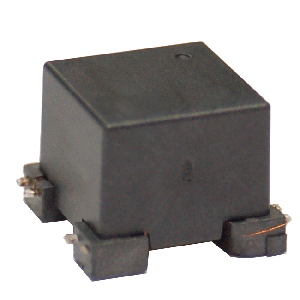
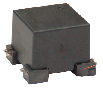
This post adds specific quality, materials, performance, and reliability requirements for the 3DCoilCubesTM EMTS (Electromagnetic Tracking Sensors) manufactured by PREMO, a leading provider of good quality components with 55 years of experience.
Design to achieve quality first
Production is bound to design, as well as design is bound to manufacture. Therefore, it’s very logical that neither a design is valid if it can’t lead to manufacture.

So there is always a trade-off between manufacturability and quality/design. The point is to keep in mind that the design should be as simple as possible, while still matching the requirements.

The best starting point not to forget about simplicity is a design based on strictly necessary materials. Manufacturing coils has been always a challenging task since the competition in the passive components market is very fierce. PREMO has always tried and accomplish the simplicity target being able to manufacture simple coils using three core components: core, base and wire.
As the market evolves, its requirements do also grow and change, ant this set of three core components may run obsolete and need the addition of new components. PREMO has overcome all these challenges to keep the simplicity to use of only these three components by improving the assembling, winding, soldering, testing & packaging automatic manufacturing processes.
Simple parts should also be simple to manufacture. PREMO has also brought this concept to its plants in order to achieve the above mentioned goal.
Is it always possible to avoid any complexity to design/new components and still match the requirements?
Well, that’s a real challenge. When it’s time to add a new element to secure the requirements, add it. But again, try to come up with some simple addition.
Depending on the requirements, the proven flexibility of PREMO will fulfill the expectations for any design. The addition of a cap to some designs is a proof of simplicity in terms of winding protection and assembling expertise.
The requirements of EMTS
The foundations of the design are well known by this name. Requirements are the target to be matched by production. Mass production must be reliable. Again, the key is simplicity. How to match requirements while keeping simplicity? Well, first, let’s have a look at the requirements of an EMTS sensor.
- Isotropic magnetic field (functionality)

- Size (integration)
- Coplanarity (connection and solderability)
- Durability under extreme operation conditions (reliability)
- Mechanical resistance (reliability)
It can be assumed these are the general requirements to be matched by any EMTS device today. While bringing simplicity to design is a matter of components and their interrelation, as we have seen before, bringing simplicity to mass production is a matter of choosing the right materials (also during the design phase) that can be easily handled and assembled in the production phase by drawing simple shapes, trying to always provide an easy way to route, wind and solder cap and base.
How to make a good decision then? What is the best for mass production? Some hints will be provided for each component.
Core
Core material will determine the EM properties of our sensor. Regarding production, the core should be as robust as possible and should have a size enough to be easily handled: not too big or too small. The handling of ferrite cores – which are fragile – during the manufacturing process – assembling – has been one of the best skills proven by PREMO. The core shape can ease the assembly and winding process, so this may be designed taking this into consideration, as the winding process can be adapted to match requirements of isotropy as needed.
SMT Base
Regarding the SMT base, three special concerns have to be taken into consideration.
The SMT base, normally plastic injected, should feature a simple pad drawing in order to ensure its coplanarity and solderability easily.
The SMT base should have a simple surface drawing in order to ease the ferrite core assembling over it. Glue dispensation processes will be much simplified if a good decision is made here.
Plastic material should match all the mechanical specifications and constraints in temperature in order not to be damaged by any curing/soldering process.
SMD
Leadframe-based
Thermoplastic with inserts
Injected thermoplastics
AOI
PTH
Gull-wing
L-inserted
L-injected
Squared/rounded
DFM techniques
With/without snap-in
With/without stand-offs
With routing and wire guides
Single/double multisection
Capped/molded/open
Thermostable/phenolic


Adhesive bonder
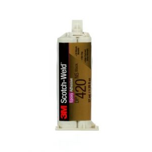
Regarding the assembly processes, the bonder to be used is a key issue. While some technical adhesives will bring complexity to the assembly process because of their difficult handling and clean dispensing, they can provide ruggedness and improved pull-off strength.
Wire
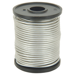
The wire is the coil. The wire, normally coated with enamel, must be properly selected because of several reasons concerning the winding process. Ideally, the risk of a broken wire should be avoided. When the diameter of the wire decreases, this risk is increased, resulting in more complicated and delicate winding and post-winding handling processes. Wire diameter should then be selected also thinking about this.
Insulation
Thermal
Bonding
- Self-bonding heat
- Self-bonding alcohol
- Not self-bonding
Solderability
- Solderable
- Not solderable
- Strippable
Strands
- Monofilar
- Bi-Multifilar
- Litz
What about the enamel coating? This decision is also important, because of the soldering and winding processes. A poor coating can lead to unintentionally short-circuited turns, resulting in magnetic field sinks, and a thick coating will bring uncertainty and dirty to the soldering process.
More about the wire: should the winding be performed directly over the core or over some other plastic surface with some supports to ease the routing and secure the winding shape? The ferrite core is a hard material. Winding processes expose the wire to a high voltage when a high winding speed is reached. This can modify the winding shape, adapting it to the form of the core, thus generating quality losses.

Tin
Tin is also an important material and its melting point should definitely be considered. It will affect the results of the soldering process by compromising success rate and quality. So it is important to make a good decision here – choose the right alloy – according to the implemented soldering process.
Another way to simplify the connection process is to remove the tin. Many methods can accomplish the electrical connection in absence of tin, such as point-to-point soldering using electrodes, laser soldering, and mechanical connection without soldering, among others.
Cap
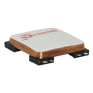
The cap is an element meant to protect the part. It can be assembled – glued – to the part and also soldered. These two different procedures may have different advantages/disadvantages. On the one hand, while assembling is simpler than soldering, since cap gluing and assembling is a low-risk process; however, it can trigger also some quality issues over almost finished products because of the effect of applying adhesive over the winding. On the other hand, soldering is a more complex process with higher scrap rates, but will guarantee the stability of inductance.
This is also an important fact in order to design the cap in order to simplify the assembly and soldering processes. Drawing of the cap should take into account soldering process limitations and provide an open soldering surface as well as a defined space to dispense the glue and let it be distributed without altering the winding shape.






Thanks for pointing out these key design considering points.