What are the challenges that most engineers face after they decide that ELECTROMAGNETIC Tracking is the best choice?
What is the Structure of a typical Tracking System?
As a closed loop control system, what are the time-domain challenges such as Stability and Error in EMTS?
What EMTS sensors are optimal for a given design?
With this post we try to help fellow VR designers to understand the first 2 questions. Keep visiting our Blog for next Post on the next two questions in a series intended to assist with the fundamentals or AC EM tracking and the best possible emitter and sensors.
A first taste of virtual reality
The tools of state of the art media are excellent at portraying human experience- a clear evidence is computer generated special effects in movies or a better example the big success of James Cameron movie Avatar ( 2009) with its amazing combination of technology and the first large introduction to mass public of the possibilities of Virtual Reality. VR is the next step in man-made verisimilitude. A face covering display (or at least goggles) takes over a user’s sense of sight, while sensors mimic the body’s subconscious mechanisms responsible for balance. The result is being someplace when you are not. VR proponents go further into Augmented Reality and say that liberating computers, tablets and smart phones from the confines of glass rectangles will change the ways in whichpeople interact with information . Alex Kipman, the inventor of Microsoft HoloLens and Kinect, as recently as 5 days ago said in an interview with Bloomberg that this is going to end with the smart phones as we know them today .
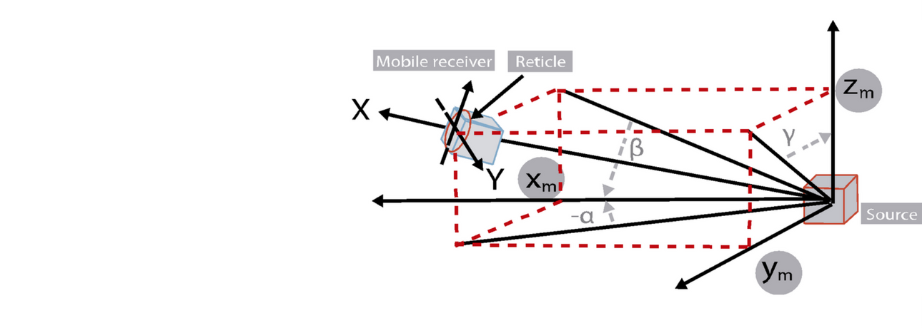
According to Faradays Law, when a receiver sensor moves in the space inside an alternating (AC) magnetic field B ( T), a voltage, proportional to the vectorial or cross product of the cross sectional winding area and the intensity of the magnetic field, is induced in every winding this producing N times the total voltage across the coils ( being N the number of turns of the winding). This induced voltage immediately gives the measurement of rotation (ɵ)vs the reference emitter coils and the position (as the modulus of the resulting vector) in relation with the modulus of the emitting vector (r) .

Therefore, EMTS ElectroMagnetic Tracking Systems can accurately calculate position and orientation as described in above figure for a 2D system. In a 3D system the process is identical but in R3 and can provide dynamic, real-time measuring position and orientation angle. This system is mainly used in Digital fields such as navigation, ballistic tracking, biomechanics, contruction, robotics, biomechanics, advance education, and above all Virtual Reality and Augmented reality systems to represent in the Digital ( Virtual) World the exact position and movements of physical objects or people, making their avatar move identically as their original physical characters.
A Tracking System Case for analysis
Electromagnetic tracking systems are composed of 4 functional moduli:
- TX circuit.
- RX circuit.
- DSP (Digital Signal Processing).
- MCU (Micro-Controller Unit) based on a PC, a Gaming Set Top Box, a Smart portable device like a Tablet or Smartphone able to run software defined algorithms
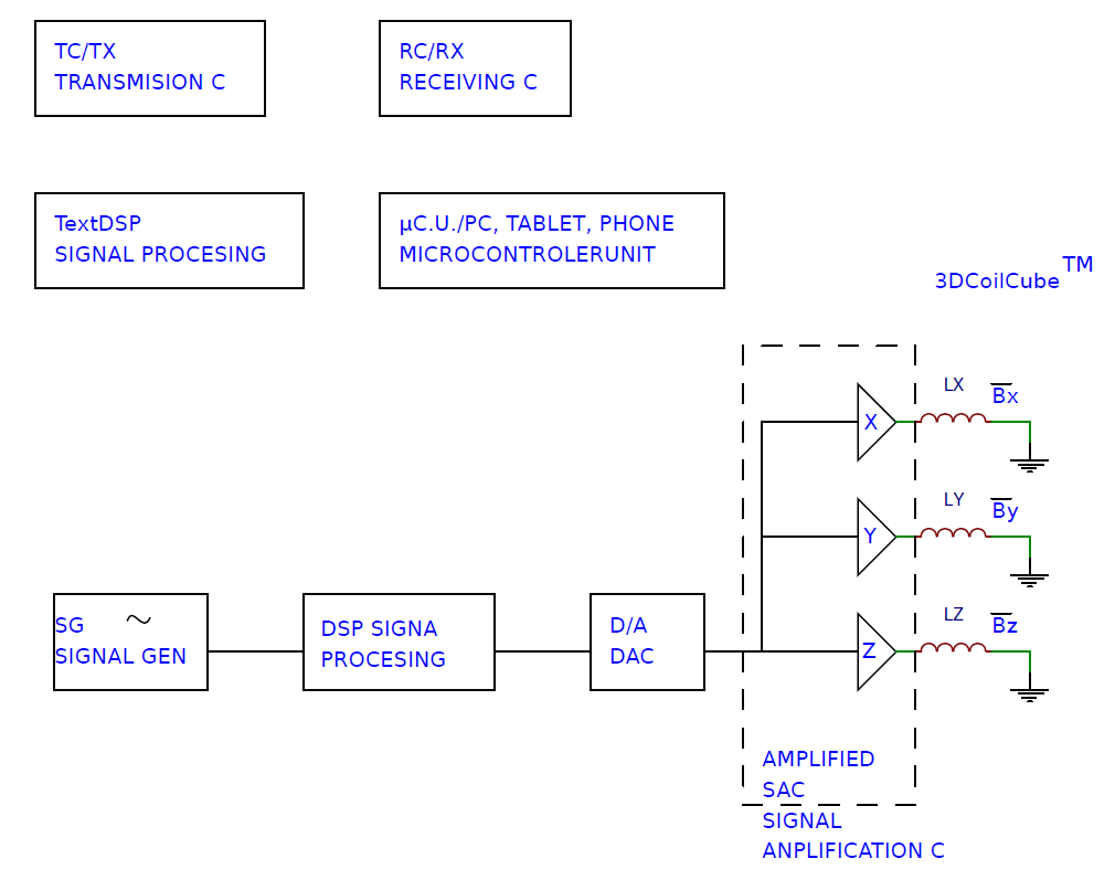
The TX Circuit contains:
- SGC or Signal Generator typically an oscillator and by frequency division a generator of LF (10KHz to 60 KHz) signal (we will cover in another post the key topic of choosing the right operating frequency).
- A simple DSP or Signal processing.
- A DAC or Digital to Analog Converter.
- An Amplifying unit or SAC to generate the 3 identical signals (?) with same amplitude, frequency, shape and shift signals that generate the 3 orthogonal magnetic fields Bx, By and Bz in the 3D TX Emitter Antenna 3DCoilcube.

The RX receiving Circuit is basically composed by :
-The EM Sensing Receiver coils
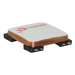
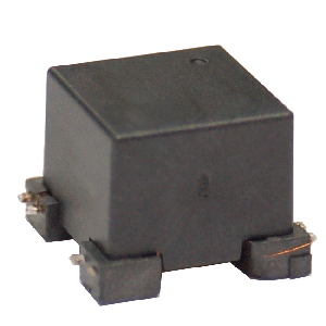
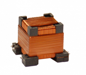
The 3 orthogonal coils wound on a cubic core (a Premo 3dCoilCubeTM) or on a low profile core (Premo 3DCoilTM) would receive voltages that are vectors with 3 orthogonal components :
Vx= k BBs + nx = k Bs · ^x + nx
Vy= k Bs · ^y + n
Vz= k Bs · ^z + nz
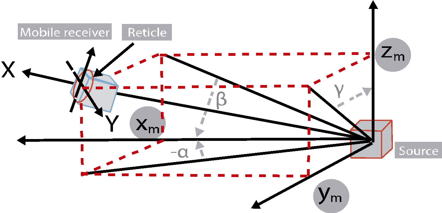
As an example : A detailed 3D Vectorial schematic for an application in a VR Cockpit Flight Simulator can be seen below:
- SAC (Signal Amplifier Circuit).
- BPF (Band Pass Filter).
- ACD (Amplitude Detection Circuit) to give us the signal amplitude that we need. The signal can be managed by the DSP, which can be embedded in the microcontroller or in a peripheral in most MCUs.
The complete system would look as follows:

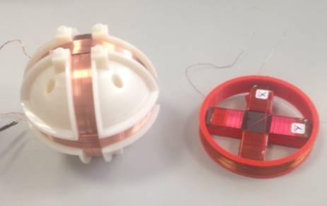
The electromagnetic emitter coil may be a spherical, a low profile or a cube. In another Post we will cover how to choose the right configuration for the Tx Electromagnetic Emitter Antennas.


The Mathematics of a 6-DOF EMTS
This example of application of 3DCoilCube and 3DCoil technology of electromagnetic tracking systems is based on a six-degree-of-freedom (6-DOF) electromagnetic algorithm. We describe the main variables and mathematics relations between them for reference.
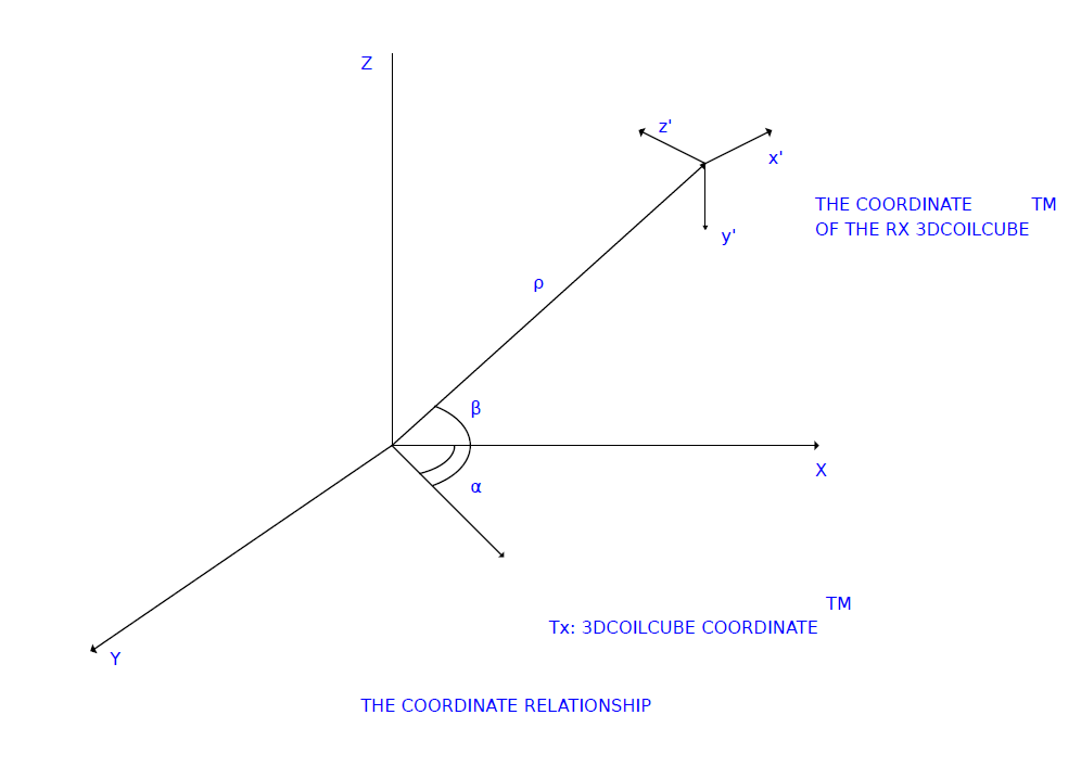
The problem is a typical vectorial configuration of two coordinates reference systems that are related (the Tx and the Rx 3DCoilcubes represent two orthogonal related systems that, as long as they are sharing the same magnetic field B, they can be linked by the spherical coordinates expressed as a 3 dimension vector (ρ,α,β) with the radius ρ and and 2 angles α,β). The rotational angles of sensing Rx 3Dcoils or 3DCoilCubes relative to the Tx Electromagnetic Emission 3Dcoilcube can be expressed as (ω,ξ,Ψ) . The definition is : first round x´makes ω degrees of horizontal rotation; then, round y´make ξ degrees of pitching rotation; at last round z´makes Ψ degrees of roll rotation. After a series of matrix transformations we can get the output formulae of ρ,α,β,ω,ξ,Ψ, hence the three important definitions of F,W & A :


P(z) in F matrix is the modulus square of Rx vector of z axis and G is the unit matrix.

Using F we can calculate the formula of ρ. Simplifying W:

Using equation 2 we can get the calculation formulae of α and β:


Using equation 3 we can get the calculation formulae of ω,ξ and Ψ:


Based on these formulas the DSP coding can be done to complete the operation of software.
The relationships between coordinates can be illustrated by the above figure and the coordinate conversion formula is as follows:

Being R the rotation matrix and T the translation matrix.
Translation:
- Moving forward and backward on the X-axis. (Surging)
- Moving left and right on the Y-axis. (Swaying)
- Moving up and down on the Z-axis. (Heaving)
Rotation
- Tilting side to side on the X-axis. (Rolling)
- Tilting forward and backward on the Y-axis. (Pitching)
- Turning left and right on the Z-axis. (Yawing)
The Reference Shelf
Bloomberg Technology, 2017, How Microsoft Jumped on Apple’s Laptop Stumbles, https://www.bloomberg.com/news/features/2017-05-03/microsoft-gets-hardware-religion, May 3rd, 2017
Retenberg, D., et Al., 2007, Portable Magnetic Position and Orientation Tracker, Sensors and Actuators, vol 135, No 2.
Ikits, M., Brederson, J.D., Hansen, C.D., and Hollerbach, J.M., 2001,An improved calibration framework for electromagnetic tracking devices, Proceedings IEEE Virtual Reality, 2001, pp. 63 -70
Caruso, M.J., et Al., 2000, Application of Magnetic Sensor for Low Cost Compass Systems, IEEE 2000. Position Locations and Navigation Symposium, San Diego March 2000
Kindratenko, V., 2000, A survey of electromagnetic position tracker calibration technique, Virtual Reality: Research, Development, and Applications, vol. 5, no. 3, pp. 169-182
Sun, S.L., et Al., 2005, The research of 6-DOF Electromagnetic Tracking System, Electronic measurement Technology, vol. 5, No. 1
Wolf, D. F., and Sukhatme, G. S., 2005, Mobile Robot Simultaneous Localization and Mapping in Dynamic Environments, Autonomous Robots, vol. 19, iss. 1, pp. 53-65
Sadjadi, H., Hashtrudi-Zaad, K., and Fichtinger, G., 2016, Simultaneous Electromagnetic Tracking and Calibration for Dynamic Field Distortion Compensation, IEEE Transactions on Biomedical Engineering [0018-9294], vol. 63, iss. 8, pp. 1771 -1781
Qin, Y., Bin, C., Run, X., Zhaoyang, C., and Bihua, Z., 2010, Research on six-degree-of-freedom electromagnetic tracking system, Antennas Propagation and EM Theory (ISAPE), 2010 9th International Symposium, pp. 1184 -1187
Anderson, P. T., 2001, An electromagnetic tracking system using printed-circuit coils, Antennas and Propagation Society International Symposium
