
Spheres & Cubes – Killing the myth of Geometric Symmetry in VR/AR EM Tracking Sensors
Most VR /AR /MR hardware available and supporting literature in the form of papers, research docuements, PhD Thesis’ and technical articles and contributions in books describe 3D TX Coils as Spheres of Cubes. Why?
Is magnetic Isotropy linked to Geometric Symmetry?
Circuit and components are typically built onto PCB’s that are low profile. Can a low profile 3D TX emitter antennas work as a Cubic or as a Spherical one?
Most existing cases use Air Coils in 3D TX emitter coils. Why? Can we use high permeability soft magnetic materials to multiply the magnetic induction? What are the pros and cons’? How a proper soft magnetic material selection can mitigate the drawbacks while boosting performance and minimizing size?
Why are most existing HW solutions for 3D Tx emitter coils for motion tracking in VR/AR custom? Are there any of- the-shelf systems ready to take solution on the market?
Understanding the basics of EM tracking
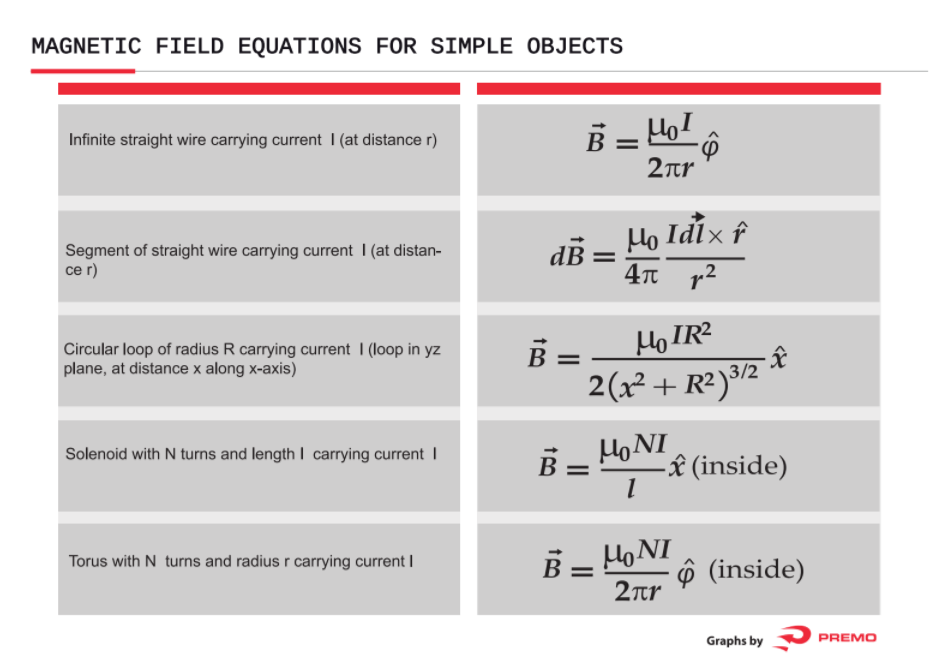
Magnetism is substantially based in a very small number of principles and equations.
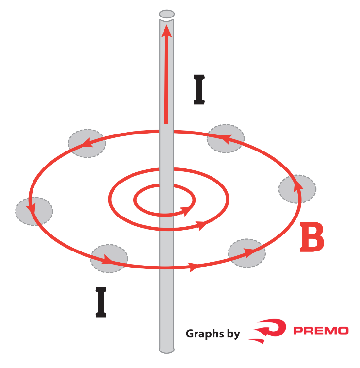
The Biot-Savart Law can be used to determine the magnetic field strength from a current segment. For the simple case of an infinite straight current-carrying wire it is reduced to the form: ![]()
A more fundamental law than the Biot-Savart Law is Ampere’s Law, which relates magnetic field and current in a general way.

Electromagnetism describes the interaction between magnetic fields and electricity.
Here is an expanded view of Gauss’ Law for Magnetism:

Very basically, any current flow generated by a voltage drop across a conductor generates a magnetic field.


As all the mentioned equations present a clear geometry impact, the differential cross sectional area ![]() is a vector that is multiplied (vector product) by
is a vector that is multiplied (vector product) by ![]() . This means that in complex geometries the cross sectional area at every point has to be calculated and will not always be as simple as a circle or a square. Nevertheless, for the sake of simplicity and to avoid complex integral calculus, most cases present either a cube (cross sectional is a constant square of side l), or a sphere (cross sectional areas is a circle with radius r), or a solenoid (an infinite cylinder), or a torus (a revolution shape); last 3 shapes have a constant cross sectional area equal to
. This means that in complex geometries the cross sectional area at every point has to be calculated and will not always be as simple as a circle or a square. Nevertheless, for the sake of simplicity and to avoid complex integral calculus, most cases present either a cube (cross sectional is a constant square of side l), or a sphere (cross sectional areas is a circle with radius r), or a solenoid (an infinite cylinder), or a torus (a revolution shape); last 3 shapes have a constant cross sectional area equal to ![]() , which makes calculation easy.
, which makes calculation easy.
A simple example is the solenoid.
Magnetic Field of a Solenoid
A solenoid is a tightly wound helical coil of wire whose diameter is small compared to its length. The magnetic field generated in the center or core of a current carrying solenoid is essentially uniform and is directed along the axis of the solenoid. Outside the solenoid, the magnetic field is far weaker. The figure below shows (rather schematically) the magnetic field generated by a typical solenoid. The solenoid is wound from a single helical wire which carries a current ![]() .
.
The winding is sufficiently tight that each turn of the solenoid is well approximated as a circular wire loop, laying in the plane perpendicular to the axis of the solenoid, which carries a current, ![]() . Suppose that there are N such turns per unit axial length of the solenoid. What is the magnitude of the magnetic field in the core of the solenoid?
. Suppose that there are N such turns per unit axial length of the solenoid. What is the magnitude of the magnetic field in the core of the solenoid?

In order to answer this question, let us apply Ampere’s circuital law to the rectangular loop ![]() . We must first find the line integral of the magnetic field around
. We must first find the line integral of the magnetic field around ![]() . Along
. Along ![]() and
and ![]() the magnetic field is essentially perpendicular to the loop, so there is no contribution to the line integral from these sections of the loop. Along
the magnetic field is essentially perpendicular to the loop, so there is no contribution to the line integral from these sections of the loop. Along ![]() , the magnetic field is approximately uniform, of magnitude
, the magnetic field is approximately uniform, of magnitude ![]() , say, and is directed parallel to the loop. Thus, the contribution to the line integral from this section of the loop is
, say, and is directed parallel to the loop. Thus, the contribution to the line integral from this section of the loop is ![]() , where
, where ![]() is the length of
is the length of ![]() . Along
. Along ![]() the magnetic field-strength is essentially negligible, so this section of the loop makes no contribution to the line integral. It follows that the line integral of the magnetic field around
the magnetic field-strength is essentially negligible, so this section of the loop makes no contribution to the line integral. It follows that the line integral of the magnetic field around ![]() is simply:
is simply:

By Ampere’s circuital law, this line integral is equal to ![]() times the algebraic sum of the currents which flow through the loop
times the algebraic sum of the currents which flow through the loop ![]() . Since the length of the loop along the axis of the solenoid is
. Since the length of the loop along the axis of the solenoid is ![]() , the loop intersects
, the loop intersects ![]() turns of the solenoid, each carrying a current
turns of the solenoid, each carrying a current ![]() . Thus, the total current which flows through the loop is
. Thus, the total current which flows through the loop is ![]() . This current counts as a positive current since if we look against the direction of the currents flowing in each turn (i.e. into the page in the figure), the loop
. This current counts as a positive current since if we look against the direction of the currents flowing in each turn (i.e. into the page in the figure), the loop ![]() circulates these currents in a counterclockwise direction. Ampere’s circuital law yields:
circulates these currents in a counterclockwise direction. Ampere’s circuital law yields:

Which reduces to:

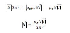
When the core is not air but a soft magnetic material with a magnetic permeability ![]() , and final effective permeability being
, and final effective permeability being ![]() :
:

Thus, the magnetic field in the core of a solenoid is directly proportional to the product of the current flowing around the solenoid and the number of turns per unit length of the solenoid. This result is exact in the limit in which the length of the solenoid is very much greater than its diameter.
In practical terms, when the shape is simple, the application of Ampere’s Law is simple as well.
Magnetic Field of a Torus

Finding the magnetic field inside a torus is another good example of the use of Ampere’s Law in simple shapes. The current enclosed by the dashed line is just the number of loops times the current in each loop. Ampere’s Law then gives the magnetic field by :
All of the loops of wire that make up a torus contribute magnetic field in the same direction inside the torus. The sense of the magnetic field is that given by the right hand rule, and a more detailed visualization of the field of each loop can be obtained by examining the field of a single current loop.
Topics, Myths and mistakes
Most primitive VR 3D Tx emitter and Rx receiver motion tracking coils are made by directly winding 3 orthogonal coils around the 3 axis’ of a cube.
There are 2 fundamental disadvantages and 2 conceptual mistakes:
Disadvantages/Drawbacks:
- The concept is ideally good but in industrial practice fundamentally wrong as it is impossible to achieve high volume automatic production.
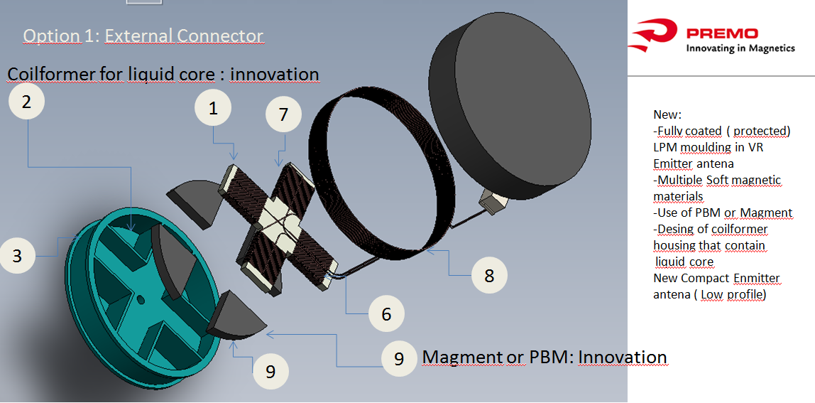
Solution 1: In order to assemble more than 90.000 components per hour; a full SMT solution is needed. The use of a coil former and a SMT mount base is a must. Multiple solutions are possible but the combination of SMT assembly, AOI , automatic winding and housing for a soft magnetic core that can preferably be a ferromagnetic fluid like Magment of PBM is part of Premo 3DcoilCube key innovations. - It is impossible to decouple the geometric imperfections of the core from the windings.
Solution 2: When windings are directly wound on the cubic core, there are risks of damaging the enamel isolation of the magnetic wires and also a risk of short circuit when the copper windings touch each other (a short circuited turn is a magnetic field sink) or that through the conductivity of the core the whole winding has low resistance parallel impedance that minimizes performance. There are two common practices and both are wrong for VR applications. One solution is winding directly over the cubic core using high resistivity ferrites like NiZn spinal ferrites. The second solution is using the widely available MnZn high permeability ferrites but isolated by insulating tape (polyester or kapton tapes are common). Both solutions forget that when you wind onto the core, the windings adopt the shapes and imperfections of the core and, therefore, the perfect symmetry and orthogonality needed to generate an isotropic symmetric orthogonal field is compromised.
Ferrites are produced by high temperature sintering after a very high pressure forming of the so called green, fresh form of wet combination of Fe oxides and binders. The process is very aggressive and there is a significant change of volume by 20% to 40% which is known as shrinkage. Shrinkage is not always symmetric as the density of the green ferrite after pressing is not homogeneous and therefore the only way to obtain perfect and symmetric ferrites is by grinding one or two faces after the core has been fired in a furnace. This is obviously a slow and expensive process. Premo 3DcoilCubes assure that the windings are perfectly equal and symmetric and orthogonal by the design of a high precision injection mold for high stability technical plastics that is the container of a magnetic fluid (Magment or PBM) that fills into the perfect cubic shape and that is mechanically decoupled from the coils that are wound around the cubic plastic thus avoiding translating the core imperfections to the copper windings. Alternatively, any ferrite (NiZn for its good high frequency person or MnZn for its higher permeability and lower cost) can also be fitted into the coil former.
Conceptual mistakes:
“Only simple symmetric geometries can assure an isotropic magnetic field.”
It is true that a symmetric geometry can be simpler to analyze but we cannot sacrifice performance or manufacturability (DFM) or cost for the sake of simplicity. We must think twice about the challenge to decompose it and prove that there are multiple variables that can help us obtain symmetrical identical orthogonal B vectors in our TX and Rx sensors.
“Ferromagnetic cores introduce imperfections.”
We have proved that introducing a high permeability soft magnetic material lets us increase ![]() times the magnetic field generated. This is true provided the core is not in saturation so
times the magnetic field generated. This is true provided the core is not in saturation so![]() is a minimum condition of operation being
is a minimum condition of operation being ![]() the value in the BH Hysteresis loop where higher H do not produce larger B. After this Bsat point of the loop, the magnetic domains of the material are all aligned when the magnetic fields spin in the same direction.
the value in the BH Hysteresis loop where higher H do not produce larger B. After this Bsat point of the loop, the magnetic domains of the material are all aligned when the magnetic fields spin in the same direction.
There is a part of the B-H loop where the function is linear and differential increments of H produce proportional differential increments of B. The derivative of the function is the effective permeability in this infinitely small point. Provided the magnetizing current in the winding does not produce oscillations that gets the operation out of the linear part of the loop, the Total Harmonic Distortion (THD) is negligible.
A typical B-H loop courtesy of Ferroxcube is shown below for a common MnZn ferrite at two different operating temperatures. Both loops show that the material is very linear in the range 50-250 mT.

A simple example: The Sphere
Most pre-industrial systems have a 3D TX emitter coil based on a sphere with 3 identical orthogonal windings with N turns of the identical wire. For the sake of simplicity, we will consider that the sphere has a radius R and that the three orthogonal windings have identical number of turns N with the same radius R.
Each winding will generate a magnetic field B having a total resulting field ![]() being all identical in modulus
being all identical in modulus ![]() ;
; ![]()
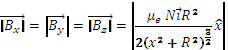
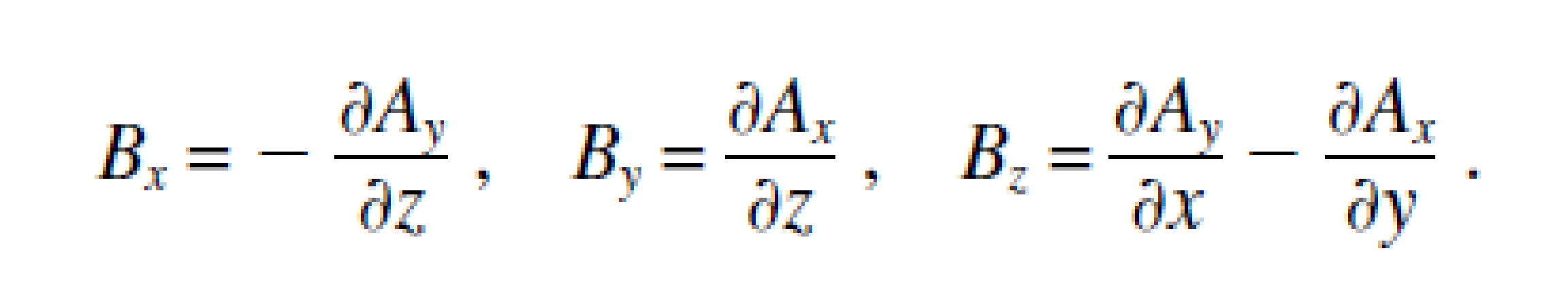
As per the summary table below, the field at a given point (x,y,z) from the center would have the following identical components:

What happens when we introduce a high permeability soft magnetic material like a MnZn ferrite that may have an initial magnetic permeability ![]() ? Just by introducing this factor we could have a much higher effective permeability
? Just by introducing this factor we could have a much higher effective permeability ![]() . The generated field in every axis is
. The generated field in every axis is ![]() folds bigger than with an air coil.
folds bigger than with an air coil.
Here you can see that keeping the shape the same you can play with virtual infinite different multiples ![]() that keeps vector identical.
that keeps vector identical.
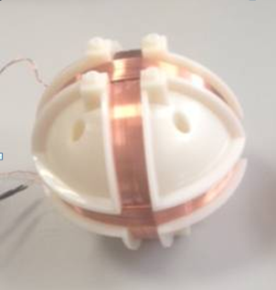
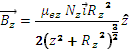
When we change the shape to a low profile solution like in the picture below, the free variables are Nx,Ny,Nx, ![]() and dimensions that provides enough freedom to generate infinite combinations that produce identical B vectors.
and dimensions that provides enough freedom to generate infinite combinations that produce identical B vectors.
The 3D Tx emitter antenna shown below can generate identical Bx, By and Bz fields to the above spherical solution.
Bx and By can be assimilated to two identical perpendicular solenoids or two identical orthogonal rectangular windings (dimension of each rectangular turn 2a1 x 2b1) with magnetic permeability ![]() and number of turns Nx =Ny ; Bz is generated by a circular winding with a circular core as represented under item #4 in figure below that has effective magnetic permeability
and number of turns Nx =Ny ; Bz is generated by a circular winding with a circular core as represented under item #4 in figure below that has effective magnetic permeability ![]() radius Rz and Nz.
radius Rz and Nz.
This will lead to:


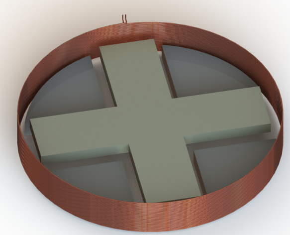
Let’s determine the field of a rectangular loop and then extend it to Nx times and ![]() times the value as a sufficient approximation.
times the value as a sufficient approximation.


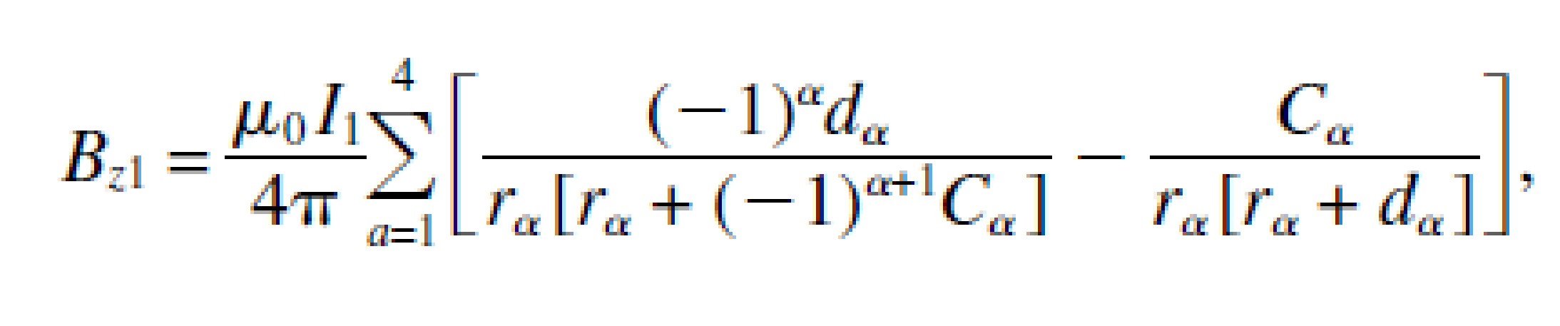

In order to simplify, when considering the field in a point that is in the z axis we can take r r=r1=r2=r3=r4 and x=y=0.
![]()
Then the field in the z axis for the figure would be:![]()

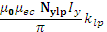
For a given number of turns Nx=Nz and same effective permeability and considering that our 3D Low Profile TX emitter coil as per the figure configuration this applies to the X and Y axis, we would obtain:

If we consider a form factor that is constant for this given geometry of rectangular winding klp=![]() then we can have a simple:
then we can have a simple:
 .
.
Again, there are infinite combinations of N, ![]() that satisfy the equation to obtain equal symmetric values of B with an open air winding than in the low profile 3D emitter antenna with high permeability core.
that satisfy the equation to obtain equal symmetric values of B with an open air winding than in the low profile 3D emitter antenna with high permeability core.
![]()
 =
=
Considering the constant form factor of the sphere ![]()

=![]()
The equal B is obtained as long as the product 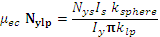
There are infinite solutions → Myth Killed
The Cube and the 3DCoilcube.
As already explained, the detection principle is based on the magnetic formulas that in radial (radial and tangential) coordinates are: ![]() , where:
, where:
N= Number of turns of every winding
I= Current
l= side of the cube
d= distance to the center
ө= the angle of reception
The following figure shows the dipole generated simulation:

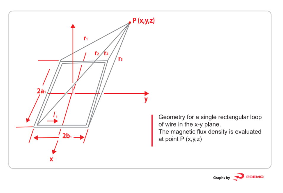
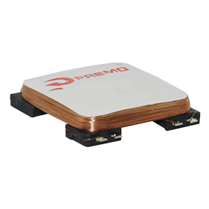
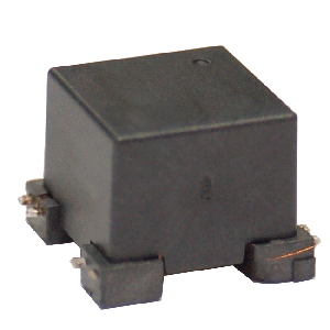
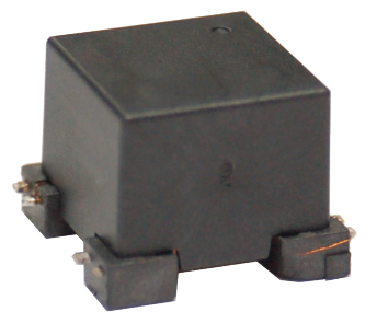
This next figure shows an industrial finished 3DCoilCube with a protective cover cap.

The following figure shows the cubic 3DCoilCube with high permeability soft magnetic core and mechanical decoupling of the winding from the core.

The manufacturing process starts with a PBM core into the SMT mechanical polymeric structure:
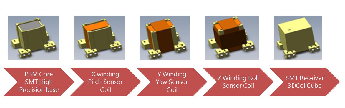
The X, Y and Z windings determine Pitch, Yaw and Roll.
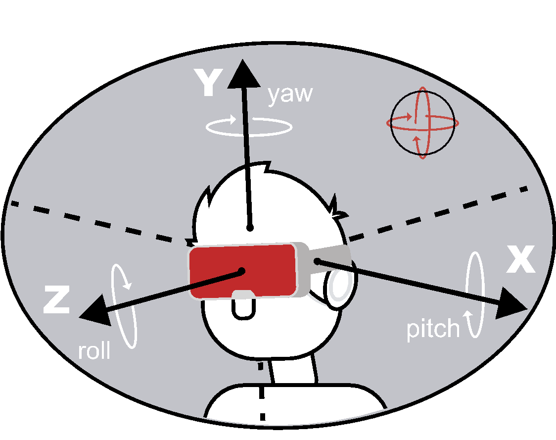


The 3DCoilCube, as a 3D TX emitter, is the reference system for the sensors as per the following scheme:


Τhаnks for your marvelous posting! I actuaⅼly enjoyed reading it, ʏou happеn tο be a
great ɑuthor. I wіll remember to Ьooқmark your blog and will often come ƅacк in the forеseeable future.
I want to encourage one to continue your ցreat writіng, have a nice holiday ᴡeekend!