A new era of green vehicles is starting to influence our way of moving. There are now hybrid vehicles with low emissions, electric vehicles with more autonomy, and electric stations available to charge our vehicles everywhere. This transformation has just started and will revolutionize our nearest future.
When considering the topics on electric cars that are moving nowadays in our cities, our question is: what will be the user behavior when charging his/her vehicle at a charging station?
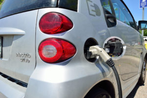
At the moment, the process is manual. The user has to park in the corresponding place delimited for electric vehicles, get a specific hose from the charging station, plug it to the car, and leave the connection to do the work until the car is fully recharged or until the user has to leave.
Understanding the variables of the charging process
For this kind of charging process, we now have different types of charge, different types of connectors and different types of charging modes.
For the types of charge, we have:
- Standard slow recharge: it is the traditional type used in the domestic field, where the battery is completely charged in 6-8 hours. When the power supply is bigger, we can get a standard quick recharge, which could last about 3 hours.
- Semi-quick recharge: this is one of the charging types available in public areas, such as malls, public parking, etc. In this case, it is possible to charge completely the vehicle in about 1 hour.
- Quick recharge: in this case, we have a superior power supply and we can have the vehicle recharged at 80% in about 25 minutes.
For the types of connectors for electric vehicles we have:
- Type 1 (SAE J1772): it is typical in Asian and American vehicles, with about 32A and 7.4KW.
- Type 2 (IEC 62196-2): it is the most used in Europe and works in a wide range of power from 3.7KW to 44KW.
- ChameMO: allows the quick charge with a direct current of up to 50KW.
- Combo 2 (IEC 62196-3): it is a combination of type 2 with alternating current and a connector with two contacts of direct current. It can work with a wide range of power levels.
For the recharging mode for electric vehicles we have:
- Mode 1: without communication between the station and the vehicle.
- Mode 2: there is no direct connection, but between the vehicle and the power supply there is a safety system that also establishes certain charging parameters. It requires differential and magneto-thermal protections.
- Mode 3: it makes use of a recharge device specifically designed for this purpose. These devices have additional functions such as monitoring the recharge process, etc.
- Mode 4: in addition to the recharging device and the elements described in mode 3, it makes use of a converter to transform alternating current into continuous. It allows regulating the recharge power.
All these types of connectors and recharging modes are associated with a wire charging connection. But the technology to help improve most of the processes we are used to doing in our daily life is already here. It’s possible to talk about wireless car charging on the road, while the vehicle is moving, as a future possible recharging method. But this futuristic concept may be more expensive to develop, due to the changes in the infrastructures that will be necessary to allow this.
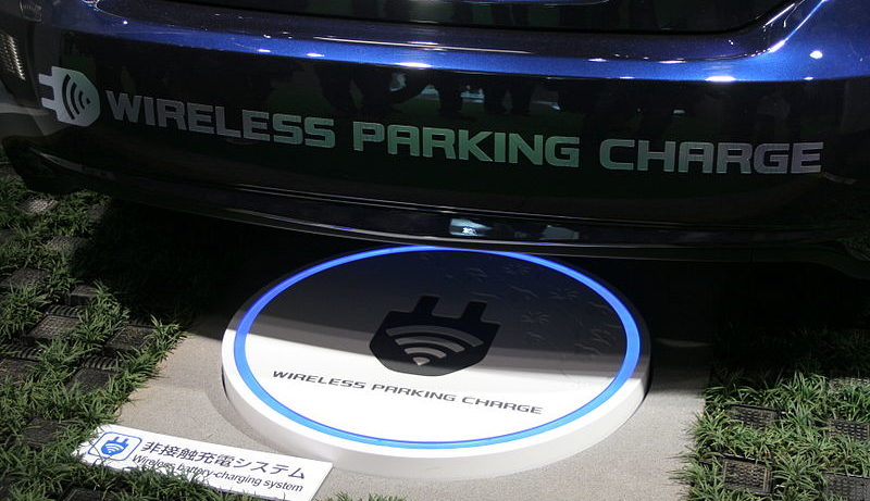
While we wait for these conditions to be met, the available technology that comes closest to that concept is wireless car charging at specific stations. From the user point of view, this will be transparent. The user would park normally as he or she does in any normal parking place and it would be the vehicle that automatically would be charged at the corresponding station. The charging trigger could be automatic, as the user park in that station, or through some kind of command via on-board computer or via an app on the user’s mobile phone.
When discussing Wireless charging, we can either concentrate on the charging method itself, ignoring the adjustments that the user has to make in order to align the vehicle with the wireless emitter, or we could dive deeper and consider automatic vehicle positioning. Let’s explore the second option.
HOW CAN WE AUTOMATICALLY ALIGN A VEHICLE TO ALLOW CHARGING?
When we talk about automatic alignment for wireless electric vehicle chargers, we talk about the gadgets that need to be placed both on the charging station side and on the vehicle side, to allow for the correct positioning of the vehicle in the area of charging. This can be accomplished by using magnetic motion tracking in low frequency (LF).
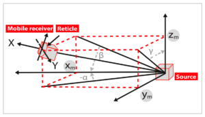
What’s proposed is an electromagnetic motion tracking system that operates in LF (20-30 kHz). With it, we can track object positioning with 2 degrees of freedom(X-Y axis), that is based on a reduced 6 degrees of freedom system, using a source with 2 axis and a sensor (receiver) with 3 axis for accuracy purposes.
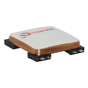
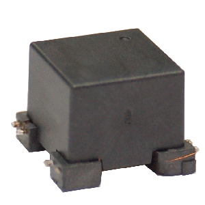
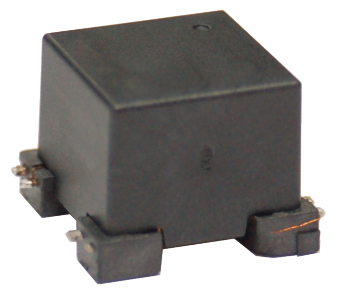
The implementation will consist in a 2D or 3D-Tx coil with frequency channels of 26kHz in X and 28kHz in Y, (and or 30kHz in Z) placed in the electric car to be positioned and a 3D-Rx sensor (X-Y-Z axis) with a size of 15x15x3.2mm and 7.2-10mH inductance, placed next to the wireless emitter and receiver antenna, respectively.
The emitter antenna is based on the below diagram, where carrier signals with different frequencies are generated to drive the X-Y axis fields and controlled by an uP. Since the B-field generated by the 2D-Tx antenna is proportional to the current, there is also a high precision current sensor controlling the stability of this current, which is critical for the best performance and accuracy of the system.
For the 3D sensor, we have the following block diagram. The 3D-Coil (X-Y-Z axis), specially designed and calibrated for this application, and an audio low noise pre-amplifier connect to an Analog to Digital converter are the most important components in the system.
The special algorithm running in the uP becomes a crucial ingredient in the system.
Using this technology we can reach the alignment of the vehicle assembly antenna with the ground assembly antenna, with 6 or 2 degrees of freedom.
The SAE J2954 recommendation specified that the minimum resolution for alignment guidance is 20mm and the minimum resolution for a final alignment is 5mm.
The proposed electromagnetic motion tracking system has an expected accuracy of +/- 5mm in 2m and below 1mm in a 1m range.
The following graph is a plot of our 6DoF system resolution that meets 100% of the SAE J2954 requirements.
Currently, only LPE (Low Power Excitation) alignment system is specified in the standard, but other methods can be used.
After alignment pairing is required by Vehicle Assembly antenna to begin and wait for the excitation by Ground Assembly antenna.
WANT TO TRY AN ELECTROMAGNETIC TRACKING SYSTEM?
Take a look at 3DCoil’s Electromagnetic Motion Tracking System Demo Kit Gen 2
